

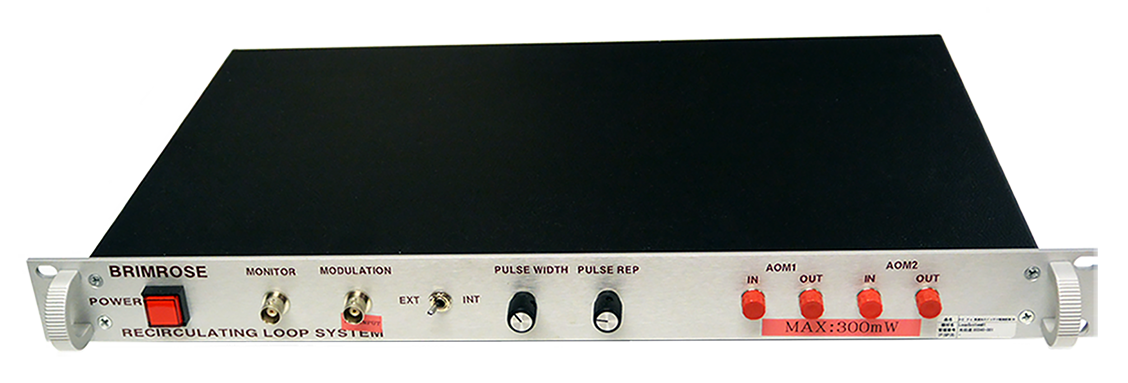
Recirculating Loop System
Brimrose Recirculating Loop System (RLS) uses two fiber‑coupled acousto‑optic (AO) modulators and a matched RF driver to control both loading and recirculation timing. The first AOM, placed outside the loop, defines the loading time. The second AOM, inside the loop, defines the recirculating time or effective transmission distance, matching the length of a long‑distance fiber‑optic link.
To prevent unwanted frequency shifts during multiple passes, the system uses a no‑shift AO device inside the loop. This keeps the optical frequency constant and ensures stable, repeatable performance without adding complexity.
Performance Capabilities
The RLS delivers performance capabilities built around its essential operational functions, supporting a broad range of application use cases. Its flexible configuration options allow the system to be adapted for specialized optical testing requirements.
Core Functions
Low Insertion Loss
No Frequency Shift
No O-rings
Rack-mount Enclosure
High Extinction Ratio >50dB
Inside Loop Recirculating Switch / Outside Loop Loading Switch
User Cases
Simulating and Testing of Long Distance Fiber Optic Communication Lines
OEM Designs
| Model # | AMM-100-4-140-1550-2FP/nfs | AMM-100-8-70-1550-2FP |
|---|---|---|
| Max. Input Optical Power (mW) | 300 | 300 |
| Polarization Dependent Loss (dB) | 0.2 | 0.2 |
| Extinction Ratio (dB) * | >50 | >50 |
| Input Impedance (ohms) | 50 | 50 |
| Case Type | 2-Port Fiber-coupled | 2-Port Fiber-coupled |
| Type of Fiber | 9µm Core, 125µm Cladding Single-Mode | 9µm Core, 125µm Cladding Single-Mode |
| Fiber Connector Type | FC/SC/LC | FC/SC/LC |
| Polishing of the Fiber End | PC/SPC/UPC/APC | PC/SPC/UPC/APC |
| Fiber Jacket Type | 900µm/3mm | 900µm/3mm |
| Back Reflection (dB) ** | 40/50 | 40/50 |
| Total Insertion Loss (dB) *** | ~5.6 | 2.5-3.0 |
Brimrose offers 2-Port Fiber-coupled AO Modulators (transmitter switch is used for outside the loop) and 2-Port Fiber-coupled AO Modulators (no frequency shift switch is used for inside the loop).
* The RF driver must match this extinction ratio.
** Back reflection at FC connector is not included.
*** This spec includes: coupling losses, optical transmission through the crystal and diffraction efficiency losses. FC connector losses are not included.
The RLS models shown in the table represent some examples of our fabrication capabilities. In addition, other wavelengths, frequencies or configurations are available.
Customers Also Consider


Product Information Request
Request detailed information on standard RLS models, or submit a custom inquiry for a customized project solution.